Flow Sensor
Design specifications
- Flow up to 2 l/s
- Volume accuracy of +- 50ml
- Capable of accurately measuring air with high oxygen concentrations
- Bidirectional flow measurement
- Sampling rate of 100 Hz
- High availability
Flow element
The most common flow sensors measure the differential pressure on both sides of an obstruction in the flow path. This obstruction is referred to as the ‘flow element’. This means that the shape of the obstruction determines the magnitude of the difference in pressure. The shape and size of the flow element are very important to get the correct pressure behaviour.

The flow element that was used for all the designs is based on the flow element of the Sensirion EK-P4 Evaluation Kit.
The behaviour of this element is documented in the Application Note of said Evaluation Kit.
A calibration graph was created, using a calibrated flow sensor (FLUKE V900A) in series.
The minimum pressure range that the flow sensor needs to measure can be determined from the equation of the curve that is fitted on the graph.

p =0,0096 N·ssl² · V2+0,4356 Nsl· V = 0,0096 · (120 sl/min)2+ 0,0096 · 120 sl/min ≈ 190 Pa
Where:
p = pressure difference from flow element in Pa
V= volumetric flow in standard liter
The total pressure range of the needed sensor should be at least ±190 Pa.
Sensor Selection
The SDP line of Sensirion has several different sensors with different pressure ranges and communication interfaces.
| chip | Pressure Range | Communication |
| SDP31 | ±500 Pa | I2C |
| SDP32 | ±125 Pa | I2C |
| SDP36 | ±500 Pa | Analog |
| SDP37 | ±125 Pa | Analog |
The SDP32 and SDP37 chips are not usable for this application due to their insufficient pressure range. The choice was made to select the SDP31 chip because of the I2C interface which is easy to implement into the electronics layout. It also bypasses faults introduced due to the A/D conversion.
SDP31 DATASHEET
https://www.sensirion.com/fileadmin/user_upload/c
ustomers/sensirion/Dokumente/8_Differential_Pressure/
Datasheets/Sensirion_Differential_Pressure_Sensors_
SDP3x_Digital_Datasheet.pdf
FLOW SENSOR CALIBRATION
The sensor can measure the airflow in two directions.
It is important to detect a difference between the inhaled and exhaled air.
The point of zero air flow must be digitally set to 0.
This calibration is done when no air is flowing during startup of the machine.
The pressure created by the flow element will differ with different gas compositions.
This has been implemented in the firmware code when extra oxygen is added to the air input.
SENSOR HOUSING
When designing the casing there are some aspects that require extra attention.
The connection between sensor and measuring points inside the tube needs to be airtight.
The connections to the tubes need to have a 22mm tapered connector (according to the ISO 5356 standard).
The flow sensor is placed very close to the patient.
Extra caution needs to be exercised to not damage the cable or connector. A strain relief is required.
In the first version of the casing, the flow and pressure sensor are located on two different PCB’s, which complicates the casing as seen above.
In newer versions, the pressure and flow sensors are located on the same pcb, which results in a smaller and cleaner design of the casing.
| V1 | V2 |
|---|---|
| Epoxy for airtight seal | Rubber seal |
| 2 PCB used for sensors | Sensors put on one PCB |

Pressure sensors
The pressure inside the lungs must be referenced against the atmospheric pressure.
To compensate for the atmospheric pressure a differential measurement shall be performed. This can be done by using a differential pressure sensor, but these are quite expensive and less common. Another possibility is using two sensors, where one measures the atmospheric pressure and the other sensor measures the pressure inside the tube.
Pressure sensor requirements are:
- Pressure range up to 80mbar over atmosphere
- Resolution of minimum 2 mBar
- Measurement of high oxygen environment
- Sampling rate of 100 Hz
- High availability
| Bme280 | Bmp280 | MPL3115A2 | |
|---|---|---|---|
| Pressure Range | 300 hPa – 1250 hPa | 300 hPa – 1100 hPa | 200 hPa – 1100 hPa |
| Pressure Resolution | 0,18 Pa | 0,16 Pa | 1,5 Pa |
| Pressure Accuracy | 1,5 hPa | 1,0 hPa | 4 hPa |
| Sampling Rate | Up to 182 Hz | Up to 157 Hz | Up to 100 Hz |
| Communication | SPI, I2C | SPI, I2C | I2C |
Caption: Comparison between pressure sensors
Based on a comparison of the specifications of the different sensors, the BME280 pressure sensor was selected, because of its extended operational range, high sampling rate and excellent availability. The MPL3115A2 is used as a backup, secondary sensor to add redundancy.
Both are wired to the same I2C bus with 3.3V signaling levels, which are then level shifted using a discrete MOSFET level shifter to 5V signaling levels.

Both pressure sensors run at 3.3V, which is provided on-board by a linear regulator of type MIC5504-3.3.
Datasheet BME280
https://ae-bst.resource.bosch.com/media/_tech/
media/datasheets/BST-BME280-DS002.pdf
Casing
This sensor is mounted together with the flow sensor on the same casing near the patient.
Sensor Interface
The sensors that are located near the patient can be as far as 3 meters away from the motherboard.
As a consequence of this distance, the resulting lengthy cables can cause the capacitive load on the bus to be too high, degrading the signal. The maximal capacitive load on the bus specified by the I2C standard is 400pF.
When the capacitive bus load exceeds 200 pF a current source is advised in place of a pull-up resistor add ref.
The solution for this problem was using an I2C-bus extender. The chip chosen for this application is the P82B715.
It increases the maximum bus load up to 3 nF.
CABLE AND CONNECTOR
The USB connector is a USB micro type specifically chosen for its ability to be made airtight using a rubber seal: https://www.digikey.com/product-detail/en/cui-devices/UJ2W-MIBH-4-SMT-TR/102-4009-1-ND/6187931
SENSOR BOARD V2
As all sensors in the module near the patient use I2C, they can be implemented on a single sensor board, and connected through the machine with a single 4-wire cable.
A single micro-USB cable is being used for this purpose.
https://circuitmaker.com/Projects/Details/Yannick-Verbelen/Breathney-Air-Sensors
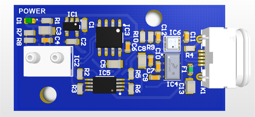

SENSOR BOARDMANUFACTURING NOTES
The same board and module is resused in the oxygen circuit.
Correct I2C-adress selection must be done in hardware by placing diferent resistors:
Adress 0x21 – use R8=0 O for main flow sensor
Adress 0x22 – use R8= 1,2 k for oxygen flow sensor
R7 should remain open.
Use R10 (connect SDO to 3.3V) to select address 0x76 – select this on oxygen flow module – Leave R9 open
Placing both R9 and R10 creates a short, do not do this.
SDO cannot be left floating.
CAD-model of the sensor module can be found on the downloads page.
PCB-design of the sensor pcb can be found on the downloads page.